
OSV-Radar
 OSV-Radar™ (see datasheet) is JRM's physics-based, real-time RF sensor scene simulator. Utilizing the popular OpenSceneGraph toolkit to load materially-encoded targets and terrain, OSV-Radar integrates JRM's SigSim and SenSim run-time libraries to predict radiometrically-correct 2D radar sensor
imagery, under arbitrary weather conditions and spatio-temporal viewing locations.
OSV-Radar is available as a binary application for Windows and Linux OS. An SDK version is also available with Source code examples to provide a fully configurable and scalable radar solution.
Physics-Based
OSV-Radar Synthesizes physics-based signatures on-the-fly from a single material-property encoded 3D database of terrain, cultural features, atmosphere and targets. User-defined physical transmitter & reciever parameters (carrier frequency, PW, PRF, polarizations, gain Distributions, power, etc.), and complex, polarized RCS data for each entity and material type, combined with atmospheric transmission & noise, are all employed to compute the at-aperture recieved power density. Entity motion and weather/wind produce corresponding Doppler effects. Finally, energy-conserving binning algorithms duplicate real radar electronics operations to form the final image.
Fully Correlated
Because OSV-Radar runs on the same spectral, material-property-encoded terrain and target database used for EO/IR wavelengths, the results are automatically fully correlated with other OSV sensor modes(e.g NVG, MWIR, LWIR).
Multiple Modes
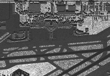
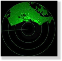
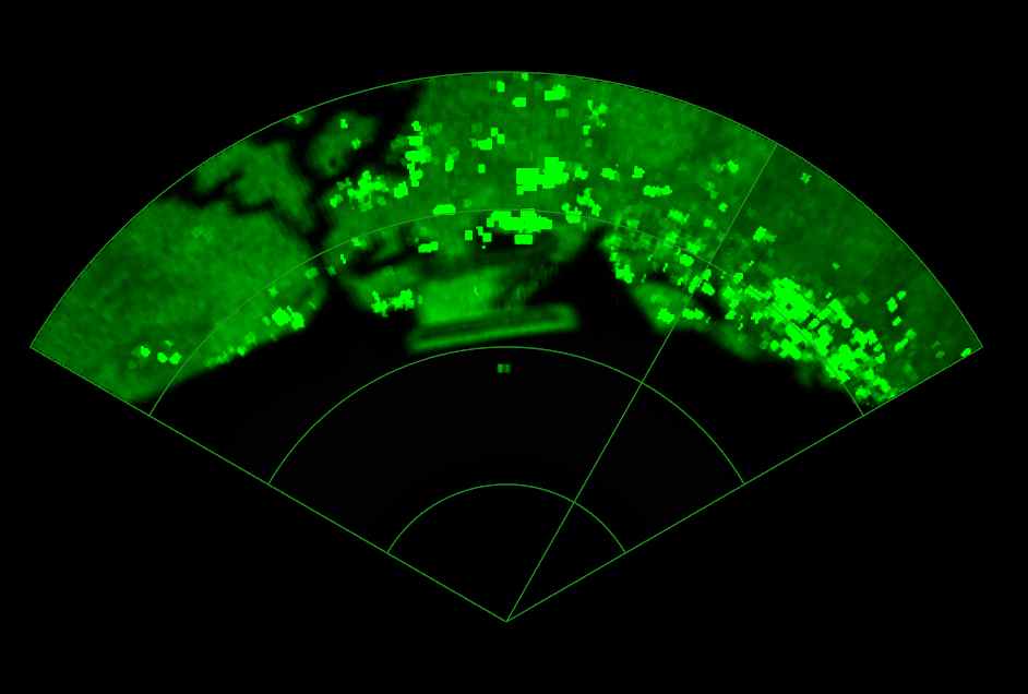
OSV-Radar supports a variety of active mode outputs, including SAR (strip and Spot), ISAR, and Wide-Area Scan with PPI display. Terrain areal RCS parameters are stored in the same material data files as are used in EO/IR modeling. RF propagation is based on RADTRAN calculations, using the same atmospheric profile specifications as for MODTRAN.
  |
 |
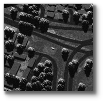
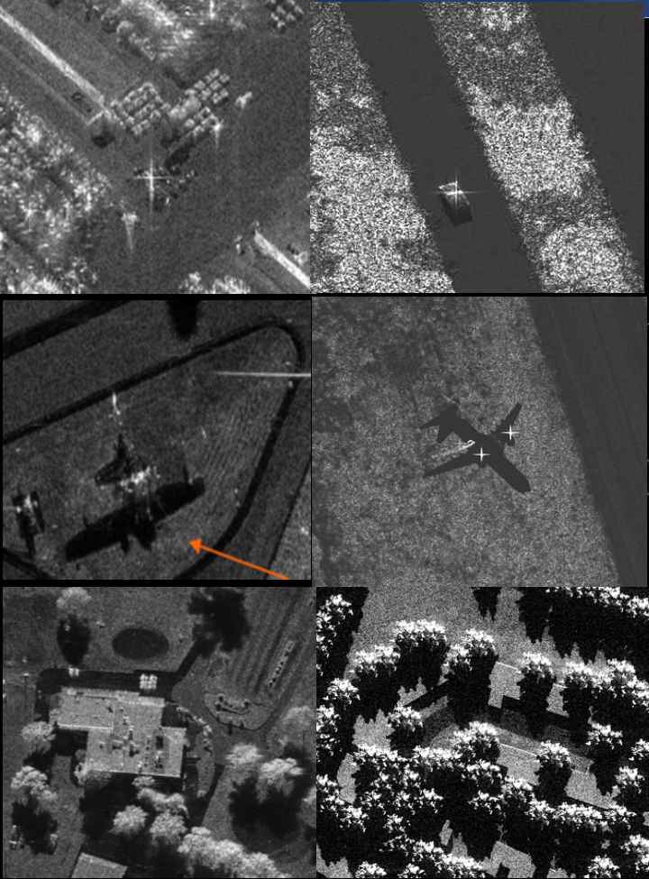
| SAR and PPI radar mode displays | Visible vs. ISAR mode |
Signature Effects
OSV-Radar includes a wide variety of real-time effects including:
- SAR Shadows & Leading edge brightness
- Down-Range/Cross-range resolution effects
- Entity motion and wind-driven Doppler
- RF path attenuation, atmospheric scattering, and absorption noise
- Vehicle radar cross-sections from imported RCS or FIELD files (user-supplied)
- Terrain areal RCS from Ulaby-Dobson parameters embedded in spectral material peoperty files (JRM MTL)
- Complex scattering and coherent summation
- Polarization
- Choice of gain distribution and directivities, for transmitter and receiver separately
- Sensor system noise as function of bandwidth and temperature
- Doppler spatial offset
Frequency Ranges
OSV-Radar provides support for the following bands:
- L-band: 1-2 GHz
- S-band: 2-4 GHz
- C-band: 4-8 GHz
- X-band: 8-12 GHz
- Ku-band: 12-18 GHz
- Ka-band: 30-40 GHz
- W-band: 90-100 GHz
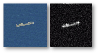
Actual Radar Image OSV Radar Image
Sensor Controls
OSV-Radar allows control over the following sensor inputs:
- Carrier frequency (GHz)
- Pulse Width (µs)
- Pulse repetition frequency-PRF (Hz)
- Transmitter polarization angle
- Transmitter gain pattern & directivity
- integration path length (m)
- Transmitter power (W)
- System temperature Saturation S/N ratio
- Display type (power, effective RCS)
- PPI sweep rate & contact threshold
- Doppler color-coding
*products contain no defense articles, classified, or export controlled (ITAR) data.